
品牌
*注:按产品型号,可检索常见问答、样本、证书等信息。

Accelerometer TP-ACC20 Measure acceleration with a USB oscilloscope.

The Accelerometer TP-ACC20 is a dual axis accelerometer combined with a manual trigger button, designed to be used with the Handyscope HS3, Handyscope HS4, Handyscope HS4 DIFF, Automotive scope ATS5004D (order code TP-ACC20-25) and Handyscope HS5 (order code TP-ACC20-09).
The dual accelerometer is a low power dual axis accelerometer with voltage outputs. It can measure accelerations in two axes, up to ± 2 g. It can measure both dynamic acceleration and static acceleration (gravity).
The manual trigger button can be used to trigger measurements in situations where no trigger condition can be derived from the input signals.
Accelerometer TP-ACC20 key specifications
| Accelerometer TP-ACC20 |
|---|
| ± 2 g range |
| Sensitivity of 420 mV/g typical |
| 500 Hz bandwidth |
Models
The Accelerometer TP-ACC20 is available in 2 models with different connectors, a 25 pin and a 9 pin D-sub connector.
| Order code | |
|---|---|
| TP-ACC20-25 | |
| TP-ACC20-09 |
The Accelerometer TP-ACC20 - 09 can be used with the Handyscope HS5. The Accelerometer TP-ACC20 - 25 can be used with the Handyscope HS3, Handyscope HS4, Handyscope HS4 DIFF and Automotive scope ATS5004D.
Package contents
The Accelerometer TP-ACC20 is delivered with:
| Amount | Item |
|---|---|
| 1 | Accelerometer TP-ACC20 |
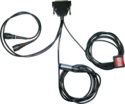
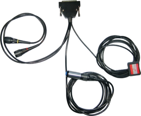
Accelerometer TP-ACC20 description
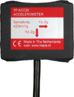
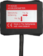
The acceleration sensor of the Accelerometer TP-ACC20 is placed in a small package with a long, thin flexible cable. The package contains strong magnets to attach the sensor to magnetic (steel) surfaces without the need of screws or clamps. One side of the package contains a patch of velcro, to attach the sensor to fabric surfaces.
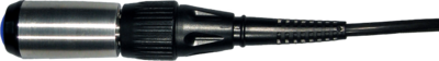
The Accelerometer TP-ACC20 also contains a manual trigger button. This button can be used to manually trigger measurements in situations where no trigger condition can be derived from the input signals. The manual trigger button has a solid aluminum body and is fitted with a male BNC connector. A long flexible cable with a female BNC connector is used to connect the button to the instrument.
Accelerometer TP-ACC20 specifications
The tables below show detailed specifications of the Accelerometer TP-ACC20. Jump to accelerometer sensor specifications, manual trigger button specifications or instrument connector specifications.
| Accelerometer sensor | |
|---|---|
| Sensor input range | ± 2 g |
| Sensitivity | 420 mV/g typical |
| Zero g bias level | 1.5 V typical |
| Zero g offset vs. temperature | < ± 0.5 mg/°C |
| Bandwidth | 500 Hz |
| Sensor resonant frequency | 5.5 kHz typical |
| Power supply | from instrument extension connector, < 0.5 mA |
| Dimensions | |
| Width | 35 mm |
| Height | 30 mm |
| Thickness | 9 mm |
| Weight | 20 g |
| Cable length | 2.5 m |
| Manual trigger button | |
| Dimensions | |
| Length (without cable) | 47 mm |
| Diameter | 18 mm |
| Connector at button | male BNC connector |
| Connector at cable | isolated female BNC connector |
| Cable length | 2 m |
| Instrument connector | |
| Connector type | Depending on model |
| Accelerometer TP-ACC20-09 | 9 pin male D-Sub connector |
| Suitable instruments | Handyscope HS5 |
| Accelerometer TP-ACC20-25 | 25 pin male D-Sub connector |
| Suitable instruments | Handyscope HS3, Handyscope HS4, Handyscope HS4 DIFF and Automotive scope ATS5004D |
| Accelerometer sensor signal connection | 2 |
| Connection | isolated female BNC connector |
| Cable length | 50 cm |
| Total weight | 200 g |
Accelerometer TP-ACC20 related articles
For more information on how to use the Accelerometer TP-ACC20, refer to the following articles.
Measuring with an accelerometer
Contents
- 1 Introduction
- 2 Requirements
- 3 Setting up the hardware
-
4 Setting up the software
- 4.1 Input sensitivity
- 4.2 Calibrating the sensor
-
4.3 Converting the measured values
- 4.3.1 Set the gain
- 4.3.2 Set the offset
- 4.3.3 Set the unit of measure
- 4.3.4 Set the alias
- 4.3.5 Connect the I/O
- 4.3.6 Set the output range
- 4.4 Measuring in m/s²
- 5 Ready to measure
- 6 Measuring speed
- 7 Measuring displacement

Download measurement setup
Download example measurement
Introduction
Acceleration measurement is used in many branches of the industry, to check and avoid vibration in mechanical systems or to track moving objects.
To measure acceleration, several different sensors are available, which convert acceleration into an electrical signal, which can be measured with a standard measuring instrument.
Requirements
The TiePie engineering Accelerometer TP-ACC20 is the ideal sensor for measuring static and dynamic accelerations in two directions. The Accelerometer TP-ACC20 is designed to work with the Handyscope HS3, Handyscope HS4, Handyscope HS4 DIFF, Automotive scope ATS5004D and Handyscope HS5. By means of two BNC connectors, the Accelerometer TP-ACC20 is connected to two inputs of the measuring instrument. Power is supplied to the Accelerometer TP-ACC20 through the D-Sub connector on the back of the measuring instrument. The Accelerometer TP-ACC20-9 features a 9 pin D-Sub connector and is suitable for the Handyscope HS5. The Accelerometer TP-ACC20-25 features a 25 pin D-Sub connector and is suitable for the Handyscope HS3, Handyscope HS4, Handyscope HS4 DIFF and Automotive scope ATS5004D. No additional cables or power supplies are required.
This measuring example describes an acceleration measurement performed with the Accelerometer TP-ACC20, connected to a Handyscope HS4, using the Multi Channel oscilloscope software.
Setting up the hardware
First the D-Sub connector of the Accelerometer TP-ACC20 must be connected to the extension connector on the rear panel of the Handyscope HS4. This connector supplies the required power to the Accelerometer TP-ACC20.
The next step is connecting the signal cables to the inputs of the Handyscope HS4. The two signal cables are color coded, red for the acceleration signal in X direction, yellow for the acceleration signal in Y direction. In this example, the X signal is connected to Ch1, the Y signal to Ch2.
The Accelerometer TP-ACC20 can measure accelerations in two axes. For initial calibration, the Accelerometer TP-ACC20 should be placed so that both axes are in their idle state, parallel to the earth's surface. To achieve this, place the Accelerometer TP-ACC20 on a stable, not moving surface, with the label facing up.
Setting up the software
Input sensitivity
When idle and not moving, the Accelerometer TP-ACC20 has an output offset of approximately 1.4 V. The Accelerometer TP-ACC20 has a typical output sensitivity of 420 mV per g acceleration and a range of approximately -2 to +2 g. This would give a maximum output voltage of almost 2.5 V. This makes the 4 V range the most suitable input range for a channel. Auto ranging is not convenient when doing acceleration measurements, therefore, switch Auto ranging off, by clicking the Auto ranging button  on the channel toolbar of the required channels.
Calibrating the sensor
When idle and not moving, the Accelerometer TP-ACC20 has an output offset of approximately 1.4 V and an output sensitivity of 420 mV per g.
To calibrate the sensor, first place it on a stable, not moving surface, with the label facing up. Use the cursors in the software to measure the offset voltage on both channels.
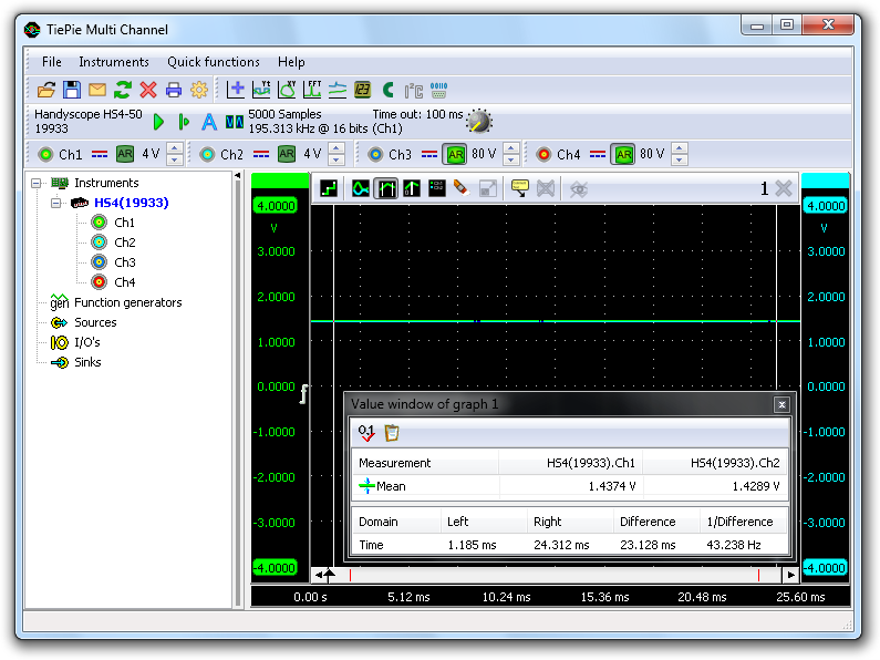
In the screen shot above, the offset value for Ch1 is 1.4374 V and for Ch2 is 1.4289 V.
To calibrate the sensitivity, a known acceleration has to be applied and the output voltage has to be measured. Since the Accelerometer TP-ACC20 is capable to measure static acceleration, it can measure the earth's gravity, being 1 g.
To measure the earth's gravity, place the sensor on a stable, not moving surface, with the X axis parallel to the earth surface and the Y axis pointing up or downwards, perpendicular to the earth surface. The Y axis, is now experiencing +1 g, measure the voltage on channel 2.
Then rotate the sensor 180 degrees around the X axis, the Y axis is now pointing down, experiencing -1 g. Measure the voltage on Ch2 again.
Repeat this with the Y axis parallel to the earth surface and the X axis pointing up and down and measure the voltages on Ch1.
As a result, six voltages are measured: +1 g, 0 g and -1 g on both axes:
| -1 g | 0 g | +1 g | |
|---|---|---|---|
| X axis | 1.0259 V | 1.4374 V | 1.8448 V |
| Y axis | 1.0382 V | 1.4289 V | 1.8598 V |
The sensitivity for a channel can now be determined with :
sensitivity = (V+1 g - V-1 g) / 2
This results in the following sensitivities: X axis = 409.45 mV/g and Y axis = 410.80 mV/g
Converting the measured values
When displaying the signal of the Accelerometer TP-ACC20 directly, the oscilloscope will display volts, not in g's or in m/s². To display the measured accelerations with unit g or m/s², the measured values need to be converted.
To convert the measured values, a Gain/Offset I/O is used for each channel of the Accelerometer TP-ACC20. Create them by right-clicking on I/Os in the object tree and selecting Gain/Offset.
Since all operations for both channels are similar, this example will only describe the settings for the X axis, Ch1.
Set the gain
As determined before, the Accelerometer TP-ACC20 has an X axis sensitivity of 409.45 mV/g. To display the measured values directly in g's, they have to be multiplied by 1 / 0.40945 = 2.4423. Right-click the X axis Gain/Offset I/O and select Gain → User defined.... There is no need to calculate the proper value for the gain, the Gain/Offset I/O can do this by itself, so simply enter "1 / 0.40945", "1/409.45m" or "1/409m45".

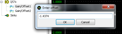
Set the offset
To compensate for the offset of the Accelerometer TP-ACC20, right-click the Gain/Offset I/O and select Input offset → User defined.... Then enter the measured offset value, multiplied by -1. In this example, the offset for the X axis is 1.4374 V, so a value of "-1.4374" has to be entered.
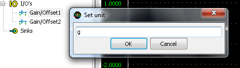
Set the unit of measure
Since gravity can be represented as g, the unit of measure should be given as g as well. To change this, right-click the Gain/Offset I/O and select Set Unit... and enter "g".
Set the alias
To simplify recognition of the various signals that can be displayed, it is possible to assign a name (alias) to an I/O. Right-click the Gain/Offset I/O and select Set alias... and enter "X axis".

Connect the I/O
The X axis Gain/Offset I/O is now ready for use. Drag input channel Ch1 of the instrument on the X axis Gain/Offset I/O and then drag the Gain/Offset I/O in the graph. The new graph shows the acceleration in one axis, directly in g. The corresponding live channel of the instrument can now be deleted from the graph. For more information, see "Creating and connecting objects".
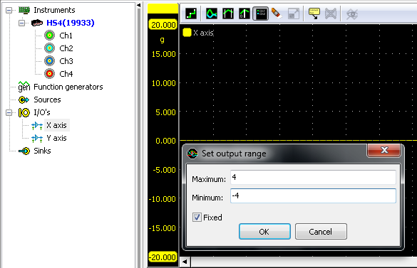
Set the output range
To customize the visible range of the converted accelerometer data, right-click the Gain/Offset I/O and select Set output range... to set the visible range to e.g. +4 to -4 g.
Measuring in m/s²
The software is currently setup to display the measured accelerations in g. To display the measured accelerations in m/s², a few adjustments have to be made in the settings of the Gain/Offset I/O.
The gain has to be set differently. Assuming that 1 g equals 9.81 m/s², the gain of the X axis Gain/Offset I/O has to be set to "9.81 * (1 / 0.40945)" in the above example. The units have to be changed from "g" to "m/s²".
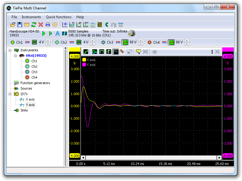
Ready to measure
The TiePie engineering Multi Channel oscilloscope software is now ready to measure both the tilt and the accelerations that the Accelerometer is experiencing.
The measurement shown below, was made with an Accelerometer TP-ACC20, sliding on a horizontal surface and bouncing against an obstacle. The measurement data and settings are saved in a Multi Channel oscilloscope software TPS file:
| File name | download |
|---|---|
| Acceleration.tps |
 |
This setfile can be opened with both the full version and the demo version of the Multi Channel oscilloscope software.
Measuring speed
When the acceleration of an object is known, as well as the initial speed of the object, it is very easy to determine the speed of the object, using an accelerometer. All one has to do is measure the acceleration in m/s² and integrate the measured data to get the speed in m/s. The Multi Channel oscilloscope software has an Integrate I/O that can be used for this task.
Create an Integrate I/O by right-clicking I/Os in the object tree and select Integrate. The alias of the Integrate I/O can be set to e.g. "X speed". Set the unit to "m/s". Then drag the X axis Gain/Offset I/O onto the Integrate I/O and drag the Integrate I/O on the graph.
The graph now displays the speed of the object, in m/s.
Measuring displacement
When the speed of an object is known, the displacement of that object can be determined very easy by integrating the speed.
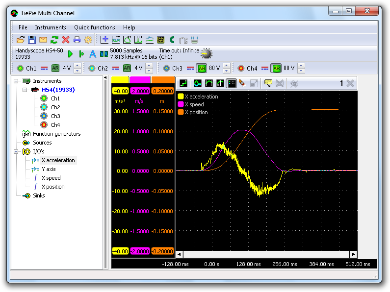
Create another Integrate I/O, name it "X position" and set the unit to "m". Now drag the X speed Integrate I/O on the X position Integrate I/O and drag the X position Integrate I/O on the graph.
The graph now displays the relative position, or displacement, of the object, in m. The image below shows a measurement with an Accelerometer TP-ACC20, which was shifted over a table, for about 15 cm.
This measurement example can be downloaded as well:
| File name | download |
|---|---|
| MeasAccel_15cm.tps |
|
Engine power measurement with accelerometer and lab scope
Contents
- 1 What is the power measurement
- 2 How do I perform a power measurement?
Download measurement
Video: Performing a power measurement
What is the power measurement
To determine whether an engine is functioning properly, a power measurement can be performed to check whether the rated power output is reached. With the Accelerometer TP-ACC20 and a lab scope, an engine power measurement can be performed with a vehicle without using a dyno or other test facilities. The power measurement can be performed during the acceleration of the vehicle.
For a power measurement with an Accelerometer TP-ACC20 and a lab scope like the Automotive scope ATS5004D, the vehicle acceleration and the total weight of the vehicle is used. The resulting power is the power that is actually transferred to the road and is being used to accelerate the vehicle.
How do I perform a power measurement?
To perform a power measurement with the Accelerometer TP-ACC20, first download the file below.
| Measurement | File |
|---|---|
| Power measurement |
|
Connect the 25 pin D-sub connector of the Accelerometer TP-ACC20 to the extension connector at the rear of the lab scope. Connect the X-axis connector of the Accelerometer TP-ACC20 to channel 1 of the lab scope and place the accelerometer level on the floor in the vehicle with the X-axis arrow pointing opposite to the driving direction, see figure 1.
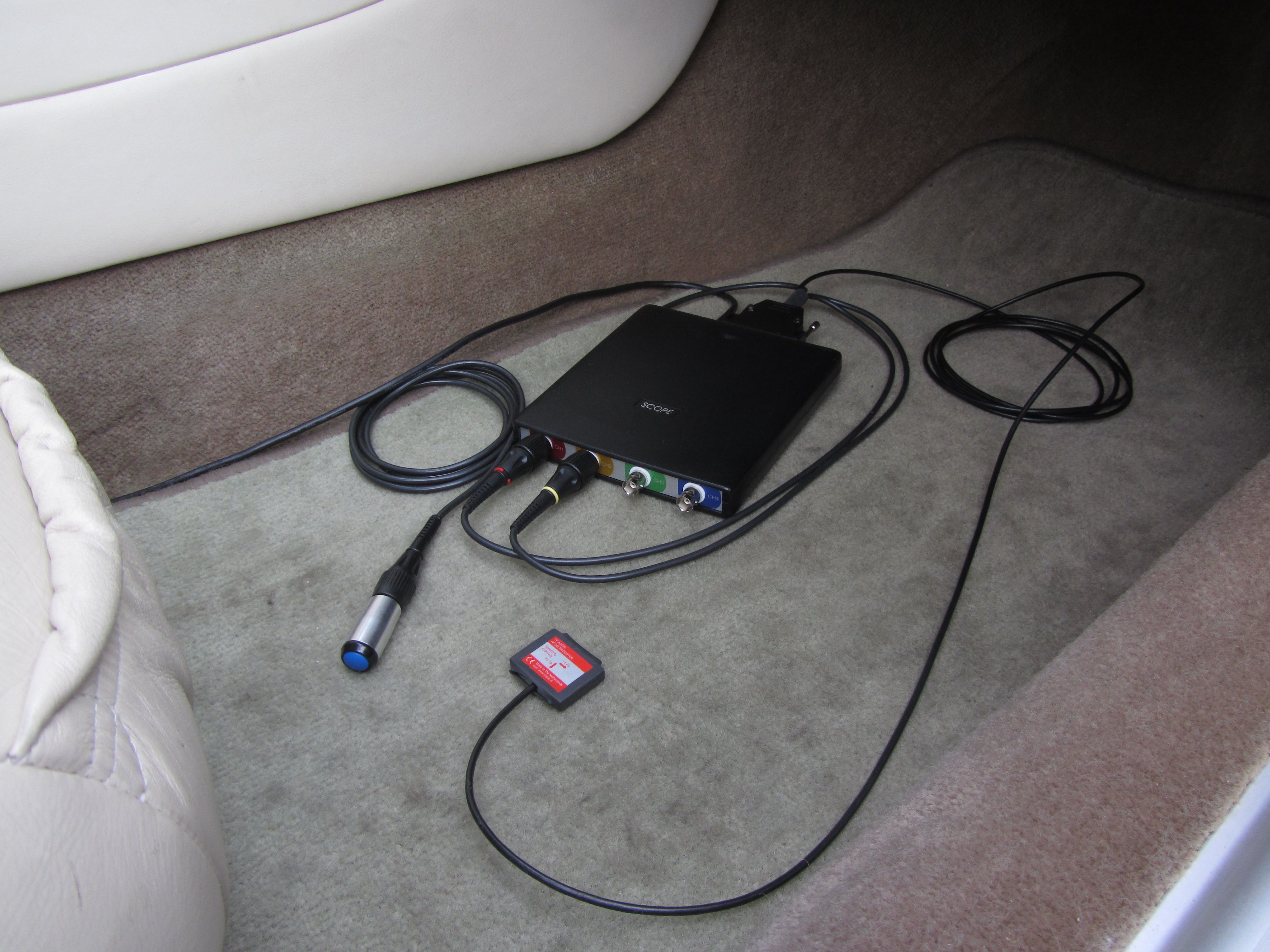 Figure 1: Placing the accelerometer in the car
Open the file in the Multi Channel oscilloscope software and proceed as follows:
- Enter the total weight of the car, including driver and passengers, in the dialog that is presented when loading the file.
- Make sure the vehicle is stationary on a horizontal road where the power measurement can be performed without causing unsafe traffic situations.
-
Click the start button
 or press hotkey S. This calibrates the accelerometer and starts the measurement.
 - Accelerate full throttle through first and second gear until it is time to select third gear.
- Immediate after the acceleration, let the vehicle roll out for about 4 or 5 seconds with the clutch pedal pressed or automatic gearbox in neutral.
-
Stop the measurement with the stop button
 or hotkey S immediately after point 5.
The power measurement is now ready and will look like figure 2.
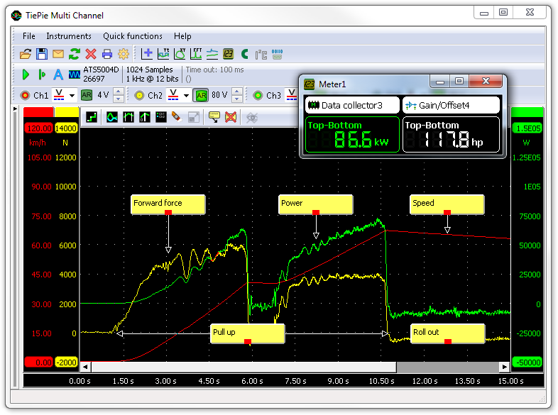 Figure 2: Engine power and speed during acceleration, measured with an accelerometer
The red signal in figure 2 shows the speed, yellow the forward force in Newtons and green the power in Watts. Meter 1 shows the total delivered engine power in kilowatt and horsepower. The maximum power in the graph is lower than the power given by meter 1 because that includes the power loss of the drive train, rolling friction and drag. It is important to let the car roll out after the acceleration to measure the negative power that is lost to overcome the various frictions. Because this power was also lost during acceleration, the real produced power of the engine is equal to the difference between the maximum and minimum measured power. This total power is displayed by meter 1 in figure 2.
Related products
-
Automotive scope ATS5004D

-
Accelerometer TP-ACC20

-
Automotive Diagnostics Kit

Related information
- Volkswagen Golf 4 accelerates with loud explosions A Golf 4 turbo GTI was having serious problems with accelerating. Accelerating from 0 to 80 km per hour would take approximately 16 seconds, which is far too long for this car. Apart from the lack of power, the engine would hold back every half second and produce a lot of explosions in the exhaust. Based on an assumption, measuring with an automotive oscilloscope was started, but it lead to no solution. When the assumption was ignored and measuring was started at the basics, the cause was found in a different area than initially was thought.
Accelerometer TP-ACC20 related products
All related products for the Accelerometer TP-ACC20 are displayed below.
-
Handyscope HS3

-
Handyscope HS4

-
Handyscope HS4 DIFF
-
Automotive scope ATS5004D

-
Handyscope HS5

-
Automotive Diagnostics Kit


工程咨询

数据中心

采油平台

发电厂

核电厂

输配电

政府及军事设施

冶金矿业

制造业

可再生能源

铁路运输系统