
品牌
*注:按产品型号,可检索常见问答、样本、证书等信息。

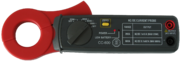
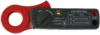
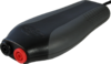
Current clamp TP-CC600 Easy to use current clamp for use with USB oscilloscope.

The Current clamp TP-CC600 is a current clamp that will allow your measuring instrument to measure electrical currents up to 600 A AC/DC, with a frequency response up to 400 Hz. When measuring with this current clamp, there is no need to break a closed circuit or to affect the isolation.
The long, narrow jaws allow performing measurements in narrow spaces.
For measuring DC current, a simple to operate zero adjust button is available.
Current clamp TP-CC600 key specifications
| Current clamp TP-CC600 |
|---|
| 600 A range |
| 0.1 mV/A |
| 3% accuracy |
| 4 mm banana sockets |
Models
The following models of the Current clamp TP-CC600 are available:
| Order code | |
|---|---|
| TP-CC600 |
Package contents
The Current clamp TP-CC600 is delivered with:
| Amount | Item |
|---|---|
| 1 | Current clamp TP-CC600 |
Current clamp TP-CC600 specifications
The tables below show detailed specifications of the Current clamp TP-CC600. Jump to electrical specifications, dimension specifications, power requirement specifications, ambient specifications or certifications.
| Electrical | |
|---|---|
| Bandwidth | DC to 400 Hz (-3dB) |
| Effective measurement range | |
| 200 A range | output 1 mV/A, 1 V = 1000 A |
| 600 A range | output 0.1 mV/A, 1 V = 10000 A |
| Accuracy | |
| DC 200 A range | ±(3% ± 0.6 A) |
| DC 600 A range | ±(3.5% ± 3 A) |
| AC 200 A range | ±(3.5% ± 0.4 A) |
| AC 600 A range | ±(4% ± 4 A) |
| Output connection | 2 shrouded 4 mm banana sockets |
| Dimensions | |
| Captured conductor size | 30 mm maximum |
| Weight | 240 g |
| Height | 30 mm (1.2 inch) |
| Length | 209 mm (8.2 inch) |
| Width | 43 mm (1.7 inch) |
| Power Requirements | |
| Power indicator | Red LED |
| Battery type | Standard 9 V IEC 6F22 cell |
| Low battery indication | Red LED |
| Ambient | |
| Operating Temperature | 0 to 50 °C |
| Relative Humidity | 25 to 70% |
| Storage Temperature | -20 to 60 °C |
| Relative Humidity | 25 to 80% |
| Certifications and Compliances | |
| CE mark compliance | Yes |
| RoHS | Yes |
Current clamp TP-CC600 related articles
For more information on how to use the Current clamp TP-CC600, refer to the following articles.
Measuring with a current clamp
Contents
- 1 Introduction
- 2 Current clamps
- 3 Connecting the current clamp
-
4 Setting up the input channel
- 4.1 Setting up the Probe settings
- 4.2 Changing the measurement unit to Amperes
- 5 Measuring DC current
- 6 Leakage detection

Introduction
To measure a current with a TiePie engineering measuring instrument with voltage inputs, the current has to be converted to a voltage related to the current. One way to do this, is to add a known resistor in the current path and measure the voltage over the resistor. This method has several drawbacks:
- The existing circuit has to be broken to add the resistor
- Adding a resistor to the circuit may affect the circuit
- Unless a differential input is used, it is not always possible to measure directly over a resistor in a circuit.
A better way to measure a current is using a current clamp, since it does not have these disadvantages.
Current clamps
A current clamp offers a way to measure the current in a conductor without the need to break the circuit. The current can be measured while maintaining a galvanic isolation between the measuring instrument and the circuit under test.
TiePie engineering offers two different current clamps:
| Model | Ranges | |
|---|---|---|
| Current clamp TP-CC80 |
 |
20 A / 80 A switchable range, AC and DC |
| Current clamp TP-CC600 |
|
200 A / 600 A switchable range, AC and DC |
Connecting the current clamp
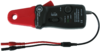
To measure a current using a current clamp, connect the current clamp to one of the inputs of the oscilloscope. The TiePie engineering current clamps have 4 mm female banana sockets. Connect the red socket to the positive terminal of the input and the black socket to the negative terminal.
Set the selector switch from the OFF position to the required input range of the current clamp. The power LED will light to indicate that the current clamp is switched on.
While the current clamp jaws are closed, press the ZERO button to reset the current clamp to zero. This will remove any offset, caused by residual magnetism remains in the core of the jaws. During zeroing, no current should flow through the clamp, so remove any wires from the clamp, or make sure no current is flowing through them.
Clamp the jaws around the current carrying conductor(s). Always make sure the jaws are tightly closed.
Setting up the input channel
The current clamp outputs a voltage that is related to the current it measures. The channel's probe gain setting can be used to convert the measured voltage to the original current value.
Setting up the Probe settings
To change the input channel settings, right-click the channel in the object tree or on the channel toolbar. This will bring up a menu with all available channel settings. To enter the relation between current and output voltage for the current clamp, select the entry Probe settings. This will bring up another menu, with some pre defined settings and a User defined... setting, which will show an input dialog in which an arbitrary value can be entered.
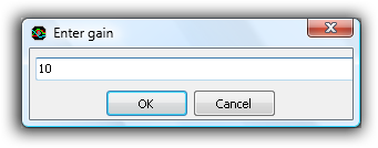
Both the Current clamp TP-CC80 and the Current clamp TP-CC600 can be used in two different current ranges, which each require their own Probe gain setting:
| Model | Range | Current - output voltage relation | Required Probe gain | Setting file | |||
|---|---|---|---|---|---|---|---|
| Current clamp TP-CC80 | 20 A | 10 A = 1 V | 10 |
 |
|||
| 80 A | 100 A = 1 V | 100 |
|
||||
| Current clamp TP-CC600 | 200 A | 1000 A = 1 V | 1000 |
|
|||
| 600 A | 10000 A = 1 V | 10000 |
|
Enter the required value from the table. The table also lists a settings file in TPS format with the appropriate settings for each current clamp, for each current range. You can download the TPS file and open it in the Multi Channel oscilloscope software to have your USB instrument setup correctly for the current clamp. These TPS files assume the current clamp is connected to input channel 1.
Changing the measurement unit to Amperes
Since current will be measured, the unit of the input channel will need to be changed. In the channel settings menu, select the entry Set unit.... This will show a dialog box in which the proper measurement unit can be entered:
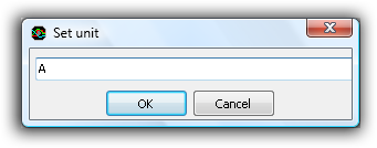
Enter an "A" here.
Measuring DC current
When measuring DC current, it is important to zero the current clamp before clamping it around the conductor. Always press the Zero button with fully closed jaws.
In case of measuring a DC current, the polarity of the output voltage depends on the current direction through the jaw of the current clamp.
| Model | Current direction1 | Output voltage |
|---|---|---|
| Current clamp TP-CC80 | Top to bottom | Positive |
| Current clamp TP-CC600 | Bottom to top | Positive |
1. Top of the current clamp is the side with the range selector switch.
Leakage detection
When more than one conductor is placed within the jaws of the current clamp, the sum of all currents flowing through the conductors is measured. Since a current clamp is direction sensitive, currents flowing in the opposite direction will be subtracted.
This makes it possible to detect a current leakage in a device. Place the clamp around all power conductors going to the device, except the earth. The sum of all currents should be zero. When the sum is not zero, there must be a current leak to earth in the device.
Relative compression test with a lab scope
Contents
- 1 What is a relative compression test?
- 2 How do I perform a relative compression test?
Download measurement
Video: Performing a relative compression test
What is a relative compression test?
Correct functioning of an engine depends on many things like e.g. correct sensor readings and good functioning actuators. But the engine itself also needs to be in good condition. With a relative compression test can easily be determined whether all cylinders of an engine have the same compression.
This relative compression test uses the starter motor current to determine the compression values of all cylinders. The advantage of a relative compression test is that no pressure sensors are needed to check each individual cylinder, all cylinders can be tested at once with just a lab scope and a current clamp.
How do I perform a relative compression test?
Before performing the relative compression test the engine needs to be prepared such it will not start during cranking.
To perform a relative compression test with a Current clamp TP-CC600, first download the file below.
| Measurement | File |
|---|---|
| Relative compression test |
|
Connect the Current clamp TP-CC600 to the lab scope Automotive scope ATS5004D with a Measure lead TP-C812B and clamp the current clamp around the wire from the battery to the starter motor, see figure 1. The direction of the wire through the clamp must be such that the starter current will introduce a positive output voltage on the clamp.
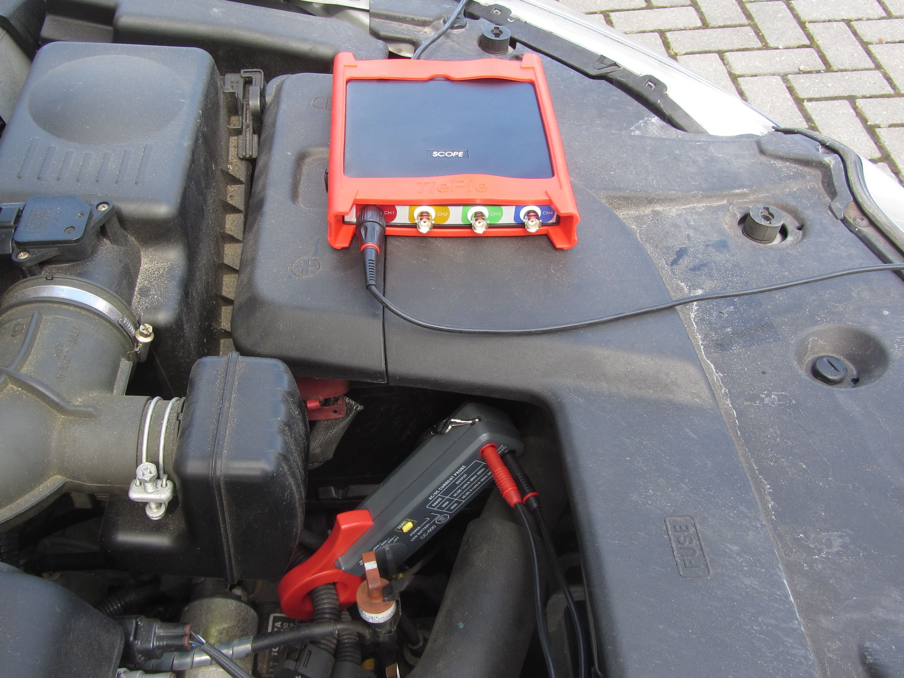 Figure 1: Setup the current clamp and lab scope for a relative compression test
Open the file in Multi Channel oscilloscope software and proceed as follows:
- Switch on the current clamp and zero the current clamp.
-
Start the measurement with the start button
 or press hotkey S.
 - Crank the engine for 2 to 4 seconds to perform the relative compression test.
The relative compression test is now ready and will look like figure 2.
 Figure 2: Result of a relative compression test
The relative compression test in figure 2 is done on a 4 cylinder engine in healthy condition. Some variations in the result of the relative compression test is acceptable.
By adding an ignition measurement to the graph, measured with channel 2, the exact cylinder can be identified with a current ramp.
Related products
-
Automotive scope ATS5004D
-
Measure lead TP-C1812B

-
Current clamp TP-CC600
-
Automotive Diagnostics Kit

Related information
- Toyota MR2 bad injector A Toyota MR2 is having problems after an engine replacement, fault code P0304 Cylinder #4 misfire detected occurs. The garage swaps several components but does not manage to fix the problem. Measurements with an automotive oscilloscope are required to find out that the fault code is somewhat misleading and the problem is not with cylinder #4
Disclaimer
This document is subject to changes without notification. All rights reserved.
The information in this application note is carefully checked and is considered to be reliable, however TiePie engineering assumes no responsibility for any inaccuracies.
Safety warning:
- Before measuring, check that sources of dangerously high voltages are switched off or shielded from contact. Voltages considered to be dangerous are voltages over 30 V AC RMS, 42 V AC peak or 60 V DC.
- Keep a clean working environment when doing measurements.
- This measurement and procedures are a examples / measuring suggestions and are no prescribed protocols.
- TiePie engineering can not anticipate the safety actions that need to be taken to protect persons and appliances. Before starting a measurement, check which safety measures need to be applied.
Related products
All related products for the Current clamp TP-CC600 are displayed below.
-
Handyscope HS3

-
Handyscope HS4
-
Handyscope HS4 DIFF
-
Handyprobe HP3
-
Automotive scope ATS5004D

-
Handyscope HS5

-
TE6100
-
Automotive Diagnostics Kit


工程咨询

数据中心

采油平台

发电厂

核电厂

输配电

政府及军事设施

冶金矿业

制造业

可再生能源

铁路运输系统