
品牌
*注:按产品型号,可检索常见问答、样本、证书等信息。

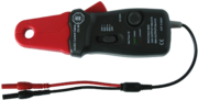
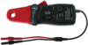
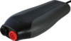
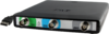
Current clamp TP-CC80 Easy to use current clamp for use with USB oscilloscope.
The Current clamp TP-CC80 is a current clamp that will allow your measuring instrument to measure electrical currents up to 80 A AC/DC, with a frequency response up to 20 kHz. When measuring with this current clamp, there is no need to break a closed circuit or to affect the isolation.
The long, narrow jaws allow performing measurements in narrow spaces.
For measuring DC current, a simple to operate zero adjust button is available.
Current clamp TP-CC80 key specifications
| Current clamp TP-CC80 |
|---|
| 80 A range |
| 10 mV/A |
| 2% accuracy |
| 4 mm shrouded banana sockets |
Models
The following models of the Current clamp TP-CC80 are available:
| Order code | |
|---|---|
| TP-CC80 |
Package contents
The Current clamp TP-CC80 is delivered with:
| Amount | Item |
|---|---|
| 1 | Carrying case |
| 1 | Current clamp TP-CC80 |
Current clamp TP-CC80 specifications
The tables below show detailed specifications of the Current clamp TP-CC80. Jump to electrical specifications, dimension specifications, power requirement specifications, ambient specifications or certifications.
| Electrical | |
|---|---|
| Bandwidth | DC to 20 kHz (-3dB) |
| Effective measurement range | |
| 20 A range | output 100 mV/A, 1 V = 10 A |
| 80 A range | output 10 mV/A, 1 V = 100 A |
| Accuracy | |
| DC 20 A range | ±(3% ±5 mA) |
| DC 80 A range |
±(3% ±0.3A) (100 mA to 40 A) ±(8% ±0.3A) (40 A to 80 A) |
| AC 20 A range |
±(3% ±5 mA) (10 mA to 10 A, 40 Hz to 2 kHz) ±(4% ±30 mA) (10 mA to 10 A, 2 kHz to 10 kHz) ±(6% ±30 mA) (10 mA to 10 A, 10 kHz to 20 kHz) ±(8% ±30 mA) (10 A to 20 A, 40 Hz to 20 kHz) |
| AC 80 A range |
±(2% ±30 mA) (100 mA to 40 A, 40 Hz to 1 kHz) ±(4% ±30 mA) (100 mA to 40 A, 1 kHz to 3 kHz) ±(6% ±30 mA) (100 mA to 40 A, 3 kHz to 20 kHz) ±(8% ±0.3 A) (40 A to 80 A, 40 Hz to 20 kHz) |
| Output connection | cable with 2 shrouded 4 mm female banana sockets |
| Dimensions | |
| Captured conductor size | 12.5 mm maximum |
| Weight | 210 g |
| Height | 38 mm (1.5 inch) |
| Length | 190 mm (7.5 inch) |
| Width | 70 mm (2.8 inch) |
| Length of cable | 30 cm (11.8 inch) |
| Power Requirements | |
| Power indicator | Green LED |
| Auto power off | Yes |
| Battery type | Standard 9 V IEC 6F22 cell |
| Battery life | 80 hours typical with alkaline |
| Low battery indication | Red LED |
| Ambient | |
| Operating Temperature | 0 to 50 °C |
| Relative Humidity | 25 to 70% |
| Storage Temperature | -20 to 70 °C |
| Relative Humidity | 25 to 80% |
| Certifications and Compliances | |
| CE mark compliance | Yes |
| RoHS | Yes |
Measuring with a current clamp
Contents
- 1 Introduction
- 2 Current clamps
- 3 Connecting the current clamp
-
4 Setting up the input channel
- 4.1 Setting up the Probe settings
- 4.2 Changing the measurement unit to Amperes
- 5 Measuring DC current
- 6 Leakage detection

Introduction
To measure a current with a TiePie engineering measuring instrument with voltage inputs, the current has to be converted to a voltage related to the current. One way to do this, is to add a known resistor in the current path and measure the voltage over the resistor. This method has several drawbacks:
- The existing circuit has to be broken to add the resistor
- Adding a resistor to the circuit may affect the circuit
- Unless a differential input is used, it is not always possible to measure directly over a resistor in a circuit.
A better way to measure a current is using a current clamp, since it does not have these disadvantages.
Current clamps
A current clamp offers a way to measure the current in a conductor without the need to break the circuit. The current can be measured while maintaining a galvanic isolation between the measuring instrument and the circuit under test.
TiePie engineering offers two different current clamps:
| Model | Ranges | |
|---|---|---|
| Current clamp TP-CC80 |
 |
20 A / 80 A switchable range, AC and DC |
| Current clamp TP-CC600 |
|
200 A / 600 A switchable range, AC and DC |
Connecting the current clamp
To measure a current using a current clamp, connect the current clamp to one of the inputs of the oscilloscope. The TiePie engineering current clamps have 4 mm female banana sockets. Connect the red socket to the positive terminal of the input and the black socket to the negative terminal.
Set the selector switch from the OFF position to the required input range of the current clamp. The power LED will light to indicate that the current clamp is switched on.
While the current clamp jaws are closed, press the ZERO button to reset the current clamp to zero. This will remove any offset, caused by residual magnetism remains in the core of the jaws. During zeroing, no current should flow through the clamp, so remove any wires from the clamp, or make sure no current is flowing through them.
Clamp the jaws around the current carrying conductor(s). Always make sure the jaws are tightly closed.
Setting up the input channel
The current clamp outputs a voltage that is related to the current it measures. The channel's probe gain setting can be used to convert the measured voltage to the original current value.
Setting up the Probe settings
To change the input channel settings, right-click the channel in the object tree or on the channel toolbar. This will bring up a menu with all available channel settings. To enter the relation between current and output voltage for the current clamp, select the entry Probe settings. This will bring up another menu, with some pre defined settings and a User defined... setting, which will show an input dialog in which an arbitrary value can be entered.
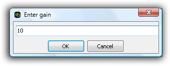
Both the Current clamp TP-CC80 and the Current clamp TP-CC600 can be used in two different current ranges, which each require their own Probe gain setting:
| Model | Range | Current - output voltage relation | Required Probe gain | Setting file | |||
|---|---|---|---|---|---|---|---|
| Current clamp TP-CC80 | 20 A | 10 A = 1 V | 10 |
 |
|||
| 80 A | 100 A = 1 V | 100 |
|
||||
| Current clamp TP-CC600 | 200 A | 1000 A = 1 V | 1000 |
|
|||
| 600 A | 10000 A = 1 V | 10000 |
|
Enter the required value from the table. The table also lists a settings file in TPS format with the appropriate settings for each current clamp, for each current range. You can download the TPS file and open it in the Multi Channel oscilloscope software to have your USB instrument setup correctly for the current clamp. These TPS files assume the current clamp is connected to input channel 1.
Changing the measurement unit to Amperes
Since current will be measured, the unit of the input channel will need to be changed. In the channel settings menu, select the entry Set unit.... This will show a dialog box in which the proper measurement unit can be entered:
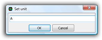
Enter an "A" here.
Measuring DC current
When measuring DC current, it is important to zero the current clamp before clamping it around the conductor. Always press the Zero button with fully closed jaws.
In case of measuring a DC current, the polarity of the output voltage depends on the current direction through the jaw of the current clamp.
| Model | Current direction1 | Output voltage |
|---|---|---|
| Current clamp TP-CC80 | Top to bottom | Positive |
| Current clamp TP-CC600 | Bottom to top | Positive |
1. Top of the current clamp is the side with the range selector switch.
Leakage detection
When more than one conductor is placed within the jaws of the current clamp, the sum of all currents flowing through the conductors is measured. Since a current clamp is direction sensitive, currents flowing in the opposite direction will be subtracted.
This makes it possible to detect a current leakage in a device. Place the clamp around all power conductors going to the device, except the earth. The sum of all currents should be zero. When the sum is not zero, there must be a current leak to earth in the device.
Measuring direct injection: servo hydraulic injector
Actuator information
| Type: | Direct injection, servo hydraulic injector |
|---|---|
| Power supply: | - |
| Signal type: | Frequency varying |
| Signal level: | 12 V to 80 V |
Download measurement
Disclaimer
Workings of a servo hydraulic injector
Today's advanced diesel engines are getting more powerful and quieter. A part of this achievement can be contributed to the way the fuel is precisely injected. Mechanical direct injection has been used in diesel engines for a long time. It can be precise, but to achieve lower emissions, it has been replaced by electronically controlled direct injection. An electronic injector can be precisely controlled by an ECU.
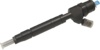
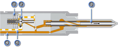 Figure 1: Servo hydraulic injector
The direct injector measured for this article is of the servo hydraulic type, pictured in figure 1. The following parts can be distinguished:
- solenoid
- control valve
- injector needle
- high pressure inlet fuel
- low pressure return fuel
Like in a classic mechanical injector, both the control valve and injector needle are being closed by a spring. The control valve is moved by the coil which is powered by the ECU when an injection is needed. The coil and control valve electrically work similar to the indirect injector. The control valve operates a hydraulic circuit which is the high pressure fuel, to control the movement of the injector needle.
When an injection is needed, the ECU opens the control valve by applying a voltage to the coil. When the control valve lifts, pressure is released from the base of the injector needle. The difference between the low pressure at the base of the injector needle and high pressure at the tip causes the needle to move from its seat and allow fuel to pass through.
To stop the injection, the control valve is closed, causing the fuel pressure at the base of the injector needle to increase, making its spring push the needle back to its closed position.
Connecting the lab scope
Correct functioning of the servo hydraulic injector can be checked by measuring the following signal voltages, see figure 2:
| Channel | Probe | Voltage | Range |
|---|---|---|---|
| 1 |
 |
Injector voltage positive side | 80 V |
 |
Injector voltage negative side | ||
| 2 |
 |
Current clamp positive connection | 4 V |
|
|
Current clamp negative connection |
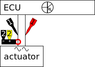 Figure 2: Measuring diagram
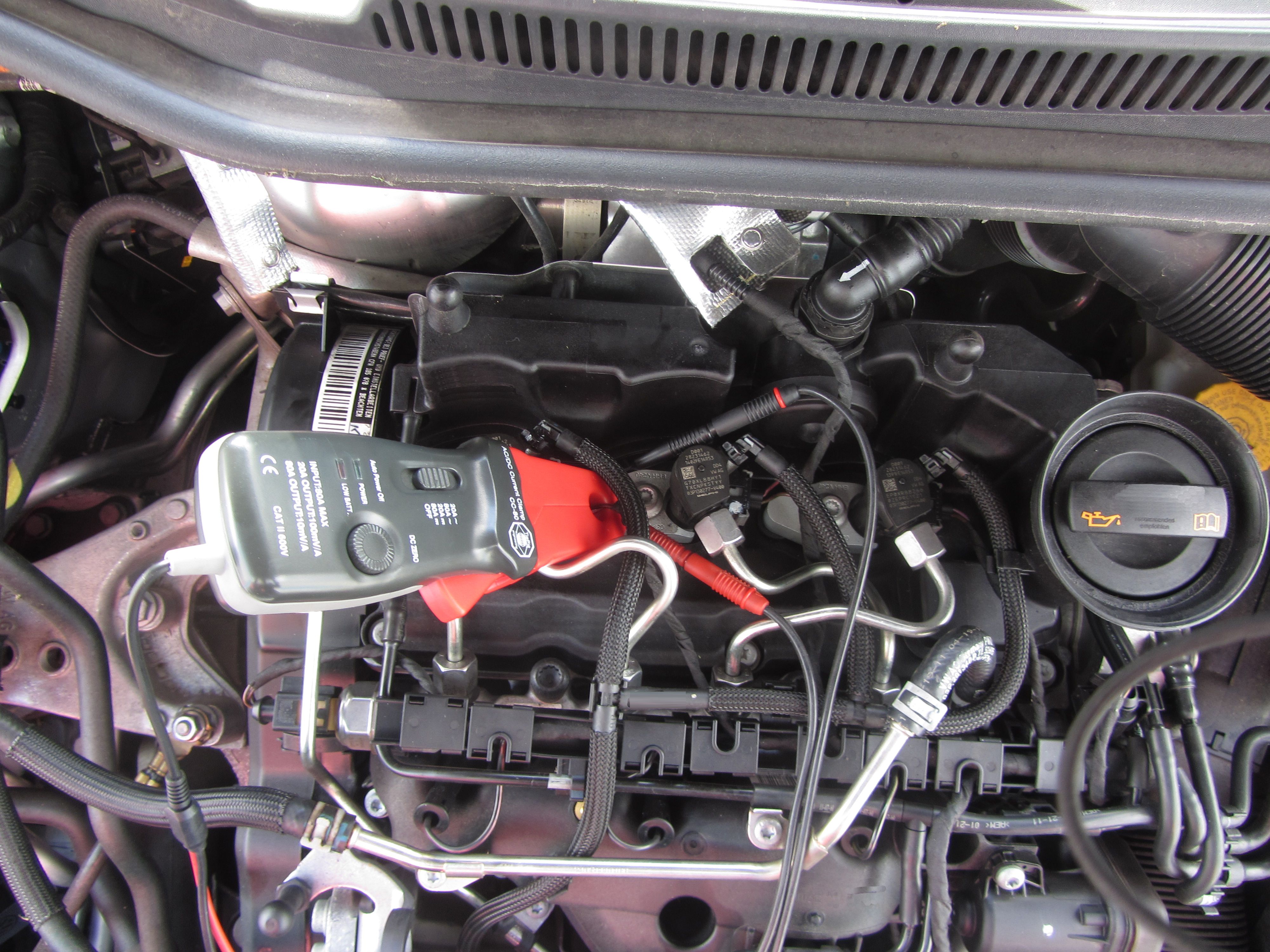 Figure 3: Measuring a working servo hydraulic injector
Channel 1 of the lab scope is connected to the servo hydraulic injector via a Measure lead TP-C1812B and Back Probe TP-BP85. The current is measured with a Current clamp TP-CC80 which is connected to channel 2 of the lab scope with the use of a Measure lead TP-C1812B. The Current clamp TP-CC80 is set to the 20 ADC range and outputs a voltage of 100 mV per 1 A. To get a readout in Amperes, the current clamp's signal voltage has to be amplified 10 times. This can be done via the menu item "probe settings" in the right click menu of channel 2. In that same menu the "Set unit..." can be used to change the unit to 'A'. The lab scope is set to normal scope mode.
Measuring
Figure 3 shows the voltage at and current through a servo hydraulic injector when idling at operating temperature. This measurement can be downloaded and used to correctly set up the lab scope or as reference signal.
| Measurement | File |
|---|---|
| Direct servo hydraulic injection measurement |
|
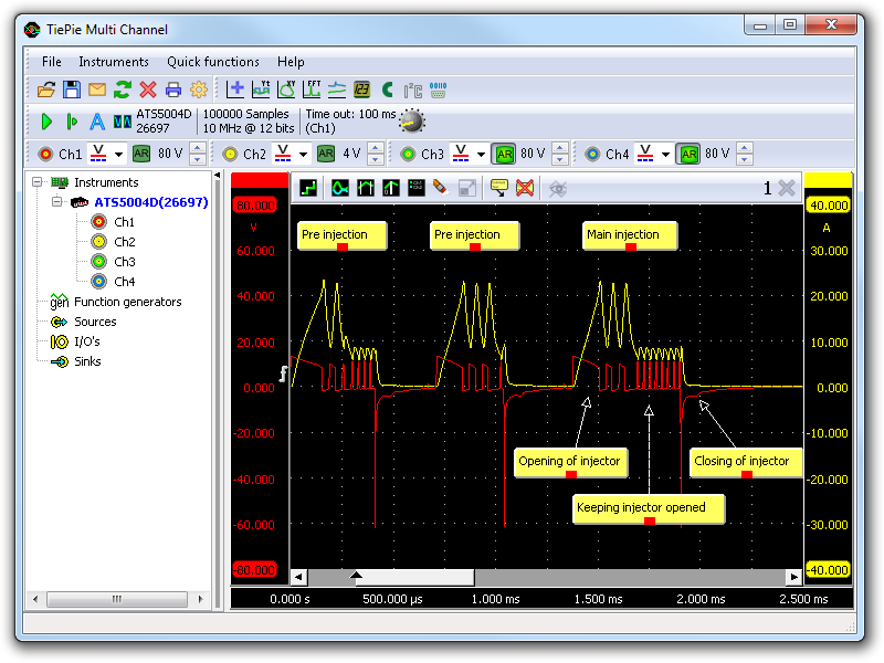 Figure 4: Lab scope measurement of servo hydraulic injector
Channel 1 (red) in figure 4 shows the injector voltage and channel 2 (yellow) the current through the servo hydraulic injector. The signals consist of three injections, of which the first two are pre injections and the last is the main injection.
Let's concentrate on the main injection visible in figure 4. The red line shows the control valve is opened with a relative long high voltage followed by two smaller pulses. The high current of around 15 A lasting for 300 µs shows the amount of energy needed to open the control valve. Once opened, the ECU keeps the control valve open by applying a low duty cycle voltage. This results in a lower current of around 8 A using less energy to keep the valve open. When the injection needs to be stopped, the ECU stops applying the voltage. A spike in the injector voltage is visible and after that a small notch which indicates the control valve is closing.
During the injection the current is high but lasts only for about 550 µs. This means that the overall applied energy is low, around 16 mJ for the main injection.
Diagnosis
Signal values may differ for different types of engine control units and servo hydraulic injectors.
The following servo hydraulic injector voltage (channel 1) deviations can indicate a problem:
-
No signal:
Cause: back probes have no connection (perform a connection test) -
Signal voltage too low:
Cause: resistance in wiring to ECU -
Noisy signal:
Cause: signal wires damaged, poor connection in connector terminals, injector defective -
Signal shows an offset in relation to the example signal:
Cause: resistance in wiring to ECU, scope is not set to DC coupling:
The following servo hydraulic injector current (channel 2) deviations can indicate a problem:
-
No signal:
Cause: current clamp not properly connected (perform a connection test), current clamp isn't switched on or has a empty battery, injector defective -
Signal voltage too high:
Cause: current clamp was not properly zeroed -
Noisy signal:
Cause: signal wires damaged, poor connection in connector terminals, injector defective -
Signal shows an offset in relation to the example signal:
Cause: current clamp was not properly zeroed
Related products
-
Automotive scope ATS5004D
-
Measure lead TP-C1812B

-
Back Probe TP-BP85

-
Current clamp TP-CC80
-
Automotive Diagnostics Kit

Related information
- Indirect injection current measurementWith a lab scope an injector current is measured on an idling engine at operating temperature. The measured current is shown and can be downloaded. To help determining whether the injector is functioning correctly, different possible deviations from the example signal are mentioned along with possible causes.
- Indirect injection voltage measurementA lab scope is used to measure an injector signal voltage on an idling engine at operating temperature. The signal from the sensor is shown and can be downloaded. To help determining whether the injector is functioning correctly, different possible deviations from the example signal are mentioned along with possible causes.
- Fuel pressure sensor and fuel metering valveWith a lab scope a fuel pressure sensor and fuel metering valve signal voltage are measured on an engine under various conditions. The signal from the fuel pressure sensor and metering valve are shown and can be downloaded. To help determining whether the fuel pressure sensor and metering valve are functioning correctly, different deviations from the example signal are mentioned along with possible causes.
Disclaimer
This document is subject to changes without notification. All rights reserved.
The information in this application note is carefully checked and is considered to be reliable, however TiePie engineering assumes no responsibility for any inaccuracies.
Safety warning:
- Before measuring, check that sources of dangerously high voltages are switched off or shielded from contact. Voltages considered to be dangerous are voltages over 30 V AC RMS, 42 V AC peak or 60 V DC.
- Keep a clean working environment when doing measurements.
- This measurement and procedures are a examples / measuring suggestions and are no prescribed protocols.
- TiePie engineering can not anticipate the safety actions that need to be taken to protect persons and appliances. Before starting a measurement, check which safety measures need to be applied.
Measuring direct petrol injector voltage and current
Actuator information
| Type: | Direct injection, coil operated |
|---|---|
| Power supply: | - |
| Signal type: | Frequency varying |
| Signal level: | -70 V to +70 V |
Workings of a direct injector
Direct petrol injection is becoming more common on internal combustion engines and replaces the indirect petrol injection to enhance engine performance and lower fuel consumption. A direct petrol injector injects the fuel directly into the combustion chamber. The injection of fuel can be done during the induction stroke for a homogeneous injection or during the compression stroke for a stratified injection.
The direct injector electrically works just like the indirect injector. The difference with the indirect injector is that the direct injector contains a low resistance coil of which both ends are connected to the ECU. The ECU contains adapted circuits to control the direct injector in such way that the opening and closing times are shortened as much as possible.
Connecting the lab scope
Correct functioning of the direct injector can be checked by measuring the following signal voltages, see figure 1:
| Channel | Probe | Voltage | Range |
|---|---|---|---|
| 1 |
|
Injector voltage positive side | 80 V |
|
|
Injector voltage negative side | ||
| 2 |
|
Current clamp positive connection | 2 V |
|
|
Current clamp negative connection |
Figure 1: Measuring diagram
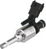
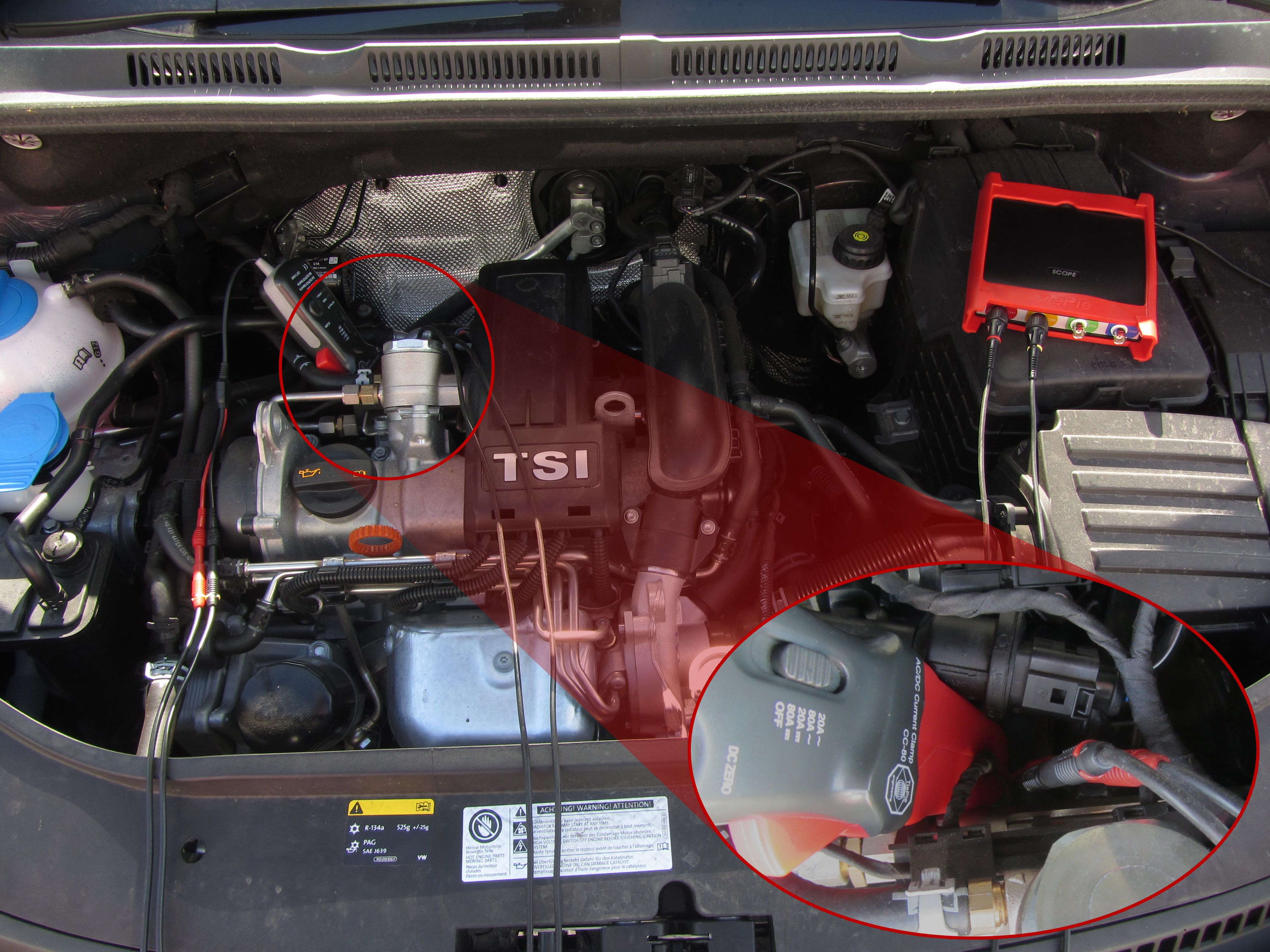 Figure 2: Measuring a working direct injector
Channel 1 of the lab scope is connected to the direct injector via a Measure lead TP-C1812B and Back Probe TP-BP85. The current is measured with a Current clamp TP-CC80 which is connected to channel 2 of the lab scope with the use of a Measure lead TP-C1812B. The Current clamp TP-CC80 is set to the 20 ADC range and outputs a voltage of 100 mV per 1 A. To get a readout in Amperes, the current clamp's signal voltage has to be amplified 10 times. This can be done via the menu item "probe settings" in the right click menu of channel 2. In that same menu the "Set unit..." can be used to change the unit to 'A'. The lab scope is set to normal scope mode.
Measuring
Figure 3 shows a waveform of the direct injector of a car with idling engine at operating temperature. This signal can be downloaded and used to correctly set up the lab scope or as reference signal.
| Measurement | File |
|---|---|
| Direct petrol injection measurement |
|
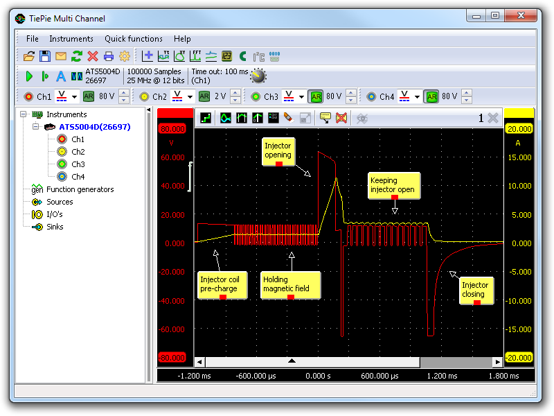 Figure 3: Lab scope measurement of direct petrol injector
In figure 3 channel 1 (red) shows the signal voltage and channel 2 (yellow) the current signal of the direct petrol injector.
Let's concentrate on the signal voltage (red). Starting form the left, the ECU applies a voltage to charge the coil with a magnetic field and shortly after applies a duty cycle signal to hold the magnetic field. This is done to minimize the time needed for opening the injector. When an injection is needed, the ECU applies a relative high voltage to open the injector as quickly as possible, after which it applies a short negative voltage to reduce the current through the coil.
After this, the coil stays powered with a duty cycle signal that is now present on the coil as can be seen in the current signal, which is higher and indicates the injector is still being held open. The current and magnetic field are kept just large enough to keep the injector open, to minimize the time needed to close the injector. When the injector needs to be closed, the ECU applies a relative high negative voltage to close it as fast as possible.
Diagnosis
Signal values may differ on different types of engine control units and direct injectors.
The following direct injector voltage (channel 1) deviations can indicate a problem:
-
No signal:
Cause: back probes have no connection (perform a connection test), direct injector defective -
Noisy signal:
Cause: signal wires damaged, poor connection in connector terminals, direct injector defective -
Signal voltage too low:
Cause: back probes have no connection (perform a connection test), resistance in wiring to ECU -
Signal shows an offset in relation to the example signal:
Cause: scope is not set to DC coupling:
The following direct injector current (channel 2) deviations can indicate a problem:
-
No signal:
Cause: current clamp not properly connected (perform a connection test), current clamp is not switched on or has a empty battery, direct injector defective -
Noisy signal:
Cause: signal wires damaged, poor connection in connector terminals, direct injector defective -
Signal shows an offset in relation to the example signal:
Cause: current clamp was not properly zeroed
Related products
-
Automotive scope ATS5004D
-
Measure lead TP-C1812B
-
Back Probe TP-BP85
-
Current clamp TP-CC80
-
Automotive Diagnostics Kit
Related information
- Indirect injection voltage measurementA lab scope is used to measure an injector signal voltage on an idling engine at operating temperature. The signal from the sensor is shown and can be downloaded. To help determining whether the injector is functioning correctly, different possible deviations from the example signal are mentioned along with possible causes.
- Direct injection servo hydraulic voltage and current measurementLab scope measurement of servo hydraulic injector voltage and current on an idling engine at operating temperature. The measured voltage and current is shown and can be downloaded. To help determining whether the servo hydraulic injector is functioning correctly, different possible deviations from the example signal are mentioned along with possible causes.
Disclaimer
This document is subject to changes without notification. All rights reserved.
The information in this application note is carefully checked and is considered to be reliable, however TiePie engineering assumes no responsibility for any inaccuracies.
Safety warning:
- Before measuring, check that sources of dangerously high voltages are switched off or shielded from contact. Voltages considered to be dangerous are voltages over 30 V AC RMS, 42 V AC peak or 60 V DC.
- Keep a clean working environment when doing measurements.
- This measurement and procedures are a examples / measuring suggestions and are no prescribed protocols.
- TiePie engineering can not anticipate the safety actions that need to be taken to protect persons and appliances. Before starting a measurement, check which safety measures need to be applied.
Measuring a current signal on an injector (indirect injection)
Actuator information
| Type: | Indirect injection |
|---|---|
| Power supply: | 12 V from system relay |
| Signal type: | Frequency and duty cycle varying |
| Signal level: | 0 A to 1 A |
Download measurement
Disclaimer
Workings of an injector
An injector sprays pressurized fuel into the inlet system or a cylinder. Due to the small opening in the injector and the high pressure, the fuel is atomized when it leaves the nozzle.
The particular injector measured for this article contains a metal pin that is kept pushed against a small opening by a spring. A coil is placed around the metal pin. A strong enough current flowing though the coil generates a magnetic field lifting the pin off the seat, opening the injector. While the current remains, the injector is held open. When the current is interrupted, the spring pressure pushes the metal pin back to its original position, closing the opening.
In most cases the injector has a power supply from a system relay and a switched ground wire connected to the ECU. In some cases the ECU controls the positive injector side and the negative side is permanently connected to ground.
A mono point injection system uses one injector placed just in front of the throttle valve. A multi point injection system uses one injector per cylinder placed in the inlet manifold just in front of the inlet port of a cylinder.
The injection moment is determined by the ECU according to the engine position which is determined from the crankshaft sensor signal and optionally the camshaft sensor signal. The ECU determines the injector's opening duration mainly from the engine temperature and demanded power.
Connecting the lab scope
Correct functioning of the injector can be checked by measuring the following signals, see figure 1:
| Channel | Probe | Voltage | Range |
|---|---|---|---|
| 1 |
|
Signal voltage at injector | 80 V |
|
|
Ground at battery | ||
| 2 |
|
Current clamp positive connection | 200 mV |
|
|
Current clamp negative connection |
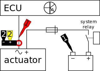 Figure 1: Measuring diagram
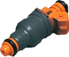
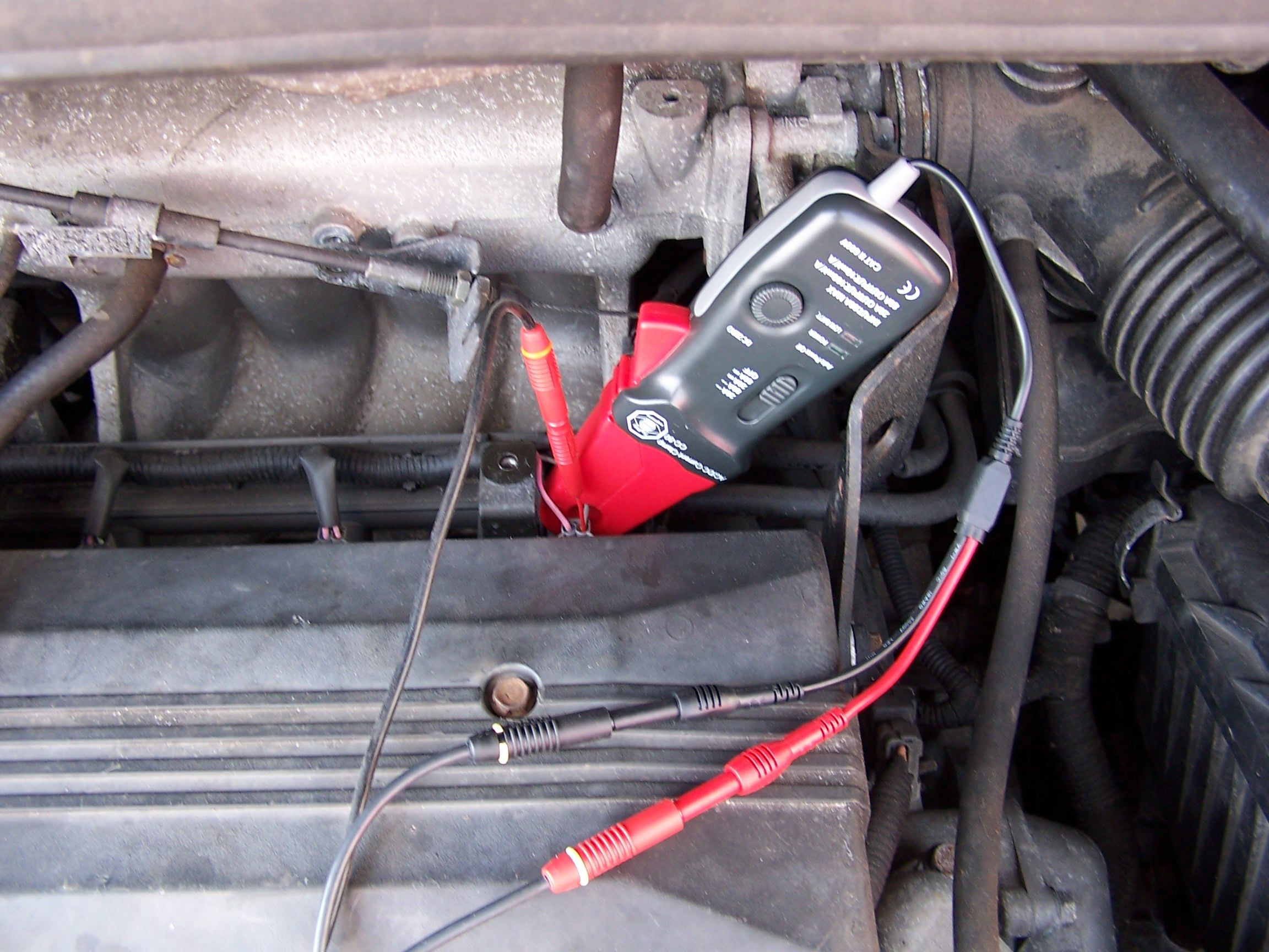 Figure 2: Measuring a working injector
Channel 1 of the lab scope is connected to the injector via a Measure lead TP-C1812B and Back Probe TP-BP85. The current is measured with a Current clamp TP-CC80 which is connected to channel 2 of the lab scope with the use of a Measure lead TP-C1812B. The Current clamp TP-CC80 is set to the 20 ADC range and outputs a voltage of 100 mV per 1 A. To get a readout in Amperes, the current clamp's signal voltage has to be amplified 10 times. This can be done via the menu item "probe settings" in the right click menu of channel 2. In that same menu the "Set unit..." can be used to change the unit to 'A'. The lab scope is set to normal scope mode.
Measuring
Figure 3 shows injector voltage and current waveforms of an idling engine at operating temperature. This signal can be downloaded and used to correctly set up the lab scope or as reference signal.
| Measurement | File |
|---|---|
| Indirect injection current measurement |
|
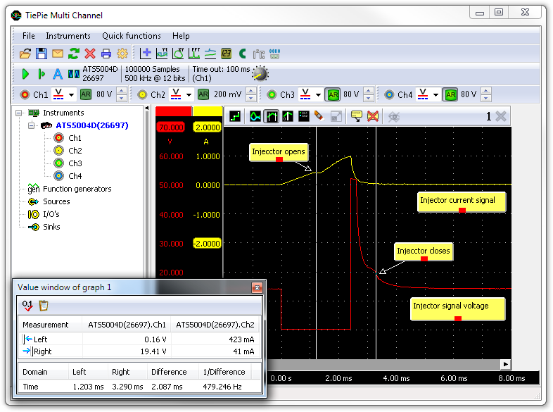 Figure 3: Lab scope measurement of injector
Channel 1 (red) shows the signal voltage of the injector about which more information can be found in the injector voltage measurement. Channel 2 (yellow) shows the current through the injector. When injector is activated by the ECU at t=0, the signal voltage drops and a current starts flowing. The current builds up a magnetic field which, when strong enough to overcome the spring pressure, lifts the pin from the seat and opens the injector. The movement of the pin trough the magnetic field is visible in the current signal, see figure 3.
When the injector has been open long enough, the circuit is interrupted by the ECU at t = 3.92 ms. At this time the current is peaking at about 1 A. Because the circuit is interrupted, the current stops immediately. The built up magnetic field slowly decreases until it is too weak to overcome the spring force, which then pushes the pin back on its seat. The movement of the metal pin changes the magnetic field which in turn affects the signal voltage. This is visible as a small hump in the signal.
Vertical cursors are used to indicate the injector's opening and closing moment. This shows that the injector has been open for a little over 2 ms.
Diagnosis
Signal values may differ on different types of engine control units and injectors.
The following signal deviations can indicate a problem:
-
No signal:
Cause: back probes have no connection (perform a connection test), current clamp isn't switched on or has a empty battery, no power supply, amplifier of ECU defective, injector defective -
Signal voltage too high
Cause: current clamp was not properly zeroed -
Noisy signal:
Cause: power supply or signal wires damaged, poor connection in connector terminals, injector defective -
Signal shows an offset in relation to example signal:
Cause: current clamp was not properly zeroed
Related products
-
Automotive scope ATS5004D
-
Measure lead TP-C1812B
-
Back Probe TP-BP85
-
Automotive Diagnostics Kit
Related information
- Indirect injection voltage measurementA lab scope is used to measure an injector signal voltage on an idling engine at operating temperature. The signal from the sensor is shown and can be downloaded. To help determining whether the injector is functioning correctly, different possible deviations from the example signal are mentioned along with possible causes.
- Toyota MR2 bad injector A Toyota MR2 is having problems after an engine replacement, fault code P0304 Cylinder #4 misfire detected occurs. The garage swaps several components but does not manage to fix the problem. Measurements with an automotive oscilloscope are required to find out that the fault code is somewhat misleading and the problem is not with cylinder #4
Disclaimer
This document is subject to changes without notification. All rights reserved.
The information in this application note is carefully checked and is considered to be reliable, however TiePie engineering assumes no responsibility for any inaccuracies.
Safety warning:
- Before measuring, check that sources of dangerously high voltages are switched off or shielded from contact. Voltages considered to be dangerous are voltages over 30 V AC RMS, 42 V AC peak or 60 V DC.
- Keep a clean working environment when doing measurements.
- This measurement and procedures are a examples / measuring suggestions and are no prescribed protocols.
- TiePie engineering can not anticipate the safety actions that need to be taken to protect persons and appliances. Before starting a measurement, check which safety measures need to be applied.
Related products
All related products for the Current clamp TP-CC80 are displayed below.
-
Handyscope HS3

-
Handyscope HS4
-
Handyscope HS4 DIFF
-
Handyprobe HP3
-
Automotive scope ATS5004D

-
Handyscope HS5
-
TE6100
-
Automotive Diagnostics Kit


工程咨询

数据中心

采油平台

发电厂

核电厂

输配电

政府及军事设施

冶金矿业

制造业

可再生能源

铁路运输系统