
品牌
*注:按产品型号,可检索常见问答、样本、证书等信息。

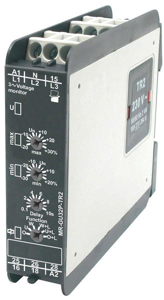

Voltage monitoring in 3-phase mains
• Multifunctions monitoring relays • Timing adjustment for tripping delay
• Fault latch mode
• Connection of neutral wire necessary
• Relay supply via the supply transformer of TR2
|
Meassuring circuit data |
|
|
Functions |
OVER, OVER+LATCH, UNDER, UNDER+LATCH, WIN, WIN+LATCH |
|
timing adjustment for tripping delay |
|
|
Time intervals (timing adjustment) |
tripping delay (0,1...10 s) |
|
LED indicator |
green LED, red LED |
|
Meassuring circuit |
|
|
• terminals |
N-L1, N-L2, N-L3 |
|
• measuring variable |
AC sinus, 48...63 Hz |
|
• measuring input |
230 V AC |
|
• overload capacity |
440 V AC |
|
• input resistance |
3N~ 400/230 V 470 kΩ |
|
• swiching threshold Us |
max: 0,8 < Un < 1,3 min: 0,7 < Un < 1,2 |
|
Input circuit |
|
|
Supply voltage U |
12 … 400 V AC; terminals A1-A2 |
|
Rated power consumption |
2,0 VA / 1,5 W |
|
Rated frequency |
as per the specification of TR2 supply transformer |
|
Output circuit |
|
|
Number and type of contacts |
2 C/O - changeover |
|
Rated load AC1 |
5 A / 250 V AC |
|
Max. breaking capacity AC1 |
1 250 VA |
|
Insulation |
|
|
Rated surge voltage |
4 000 V AC |
|
Overvoltage category |
III PN-EN 60664-0 |
|
Insulation pollution degree |
3 PN-EN 60664-1 |

工程咨询

数据中心

采油平台

发电厂

核电厂
输配电

政府及军事设施

冶金矿业

制造业

可再生能源

铁路运输系统